Dual-Mode Operation
KLSTR.nano acts as a communication bridge between KLSTR.one and the host CPU. This setup requires minimal software effort on the host fixture side because plain RDM+DMX is used as a communication protocol.
When to use dual mode
Dual mode is the right choice when:
- Your fixture needs Ethernet connectivity (Art-Net/sACN) and compact internal integration
- You want full RDM support while keeping the fixture’s internal module small
- The KLSTR.nano is embedded on the fixture PCB
Architecture
Ethernet ──► KLSTR.one ──► DMX_LAN ──► KLSTR.nano ──► Host CPU │ │ Art-Net DMX decode sACN & control RDM
The KLSTR.one converts network protocols to DMX. The KLSTR.nano receives this DMX via the DMX_LAN interface and forwards it to the host fixture’s RS485 transceiver. The KLSTR.nano also maintains the external DMX daisy-chain (DMX_IN/DMX_OUT) independently.
Connection blocks
KLSTR.nano — 6 connection blocks
The KLSTR.nano requires 6 connection blocks to work properly when used in dual mode with a KLSTR.one:
- DMX IN
- DMX OUT
- DMX LAN
- POWER — Powered via pin 17 with 5V0
- KLSTR.one Interface — USB, heartbeat signals, reset signals
- Serial Wire Debug
KLSTR.one — 5 connection blocks
The KLSTR.one requires 5 connection blocks to work properly when used in dual mode with a KLSTR.nano:
- Ethernet A–B + Ethernet Bypass Relay Circuit
- Ethernet C
- POWER — Powered via pins 84–89 with 3V3. Bypass relays powered with 5V0.
- KLSTR.nano Interface — USB, heartbeat signals, reset signals
- Console Port
Wiring
Connect DMX_LAN between the two modules
Route as a 120 Ω differential pair. Keep the connection as short as possible — DMX_LAN has no external line protection.KLSTR.one Signal KLSTR.nano Pin DMX LAN A+ RS485 A+ Pin 23 (DMX_LAN_A) DMX LAN B− RS485 B− Pin 22 (DMX_LAN_B) GND Ground Pin 21 (GND) Connect KLSTR.one/KLSTR.nano interface
The interface between the two modules includes USB, heartbeat signals, and reset signals:Signal KLSTR.nano Pin Description Heartbeat KLSTR.one Pin 35 (PC2) KLSTR.one alive signal Heartbeat KLSTR.nano Pin 32 (PB8) KLSTR.nano alive signal Reset KLSTR.nano Pin 34 (NRESET) Active-low reset for KLSTR.nano Reset KLSTR.one Pin 33 (PB9) Active-low reset for KLSTR.one USB_N Pin 14 USB port negative USB_P Pin 15 USB port positive Power each module
- KLSTR.one: 3.3 V DC via pins 84–89. Bypass relays powered with 5V0.
- KLSTR.nano: Powered via pin 17 with 5V0.
Connect Serial Wire Debug (KLSTR.nano)
KLSTR.nano Pin Label Function 16 SWDIO Programming 24 SWCLK Programming 30 PB3_SWO Programming Connect Console Port (KLSTR.one)
KLSTR.one Pin Label Function 108 GND Ground 109 TXD1 UART Lite TX Data 110 RXD1 UART Lite RX Data
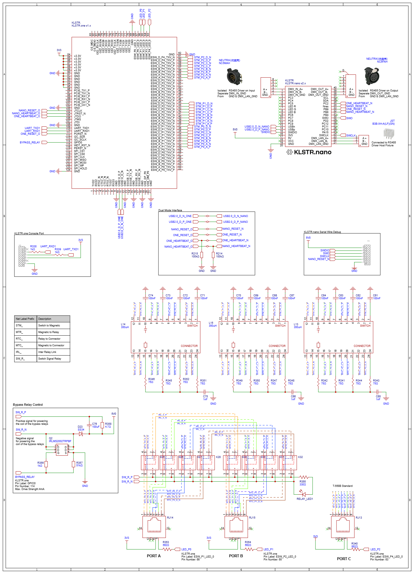
Dual mode connection schematic
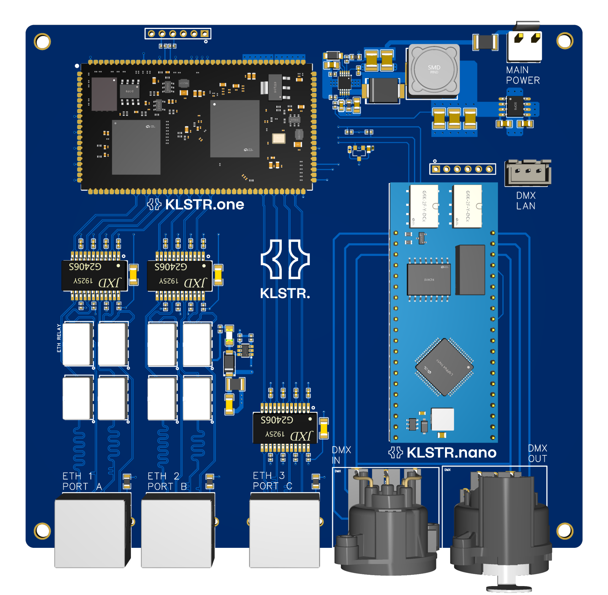
Reference board — top view
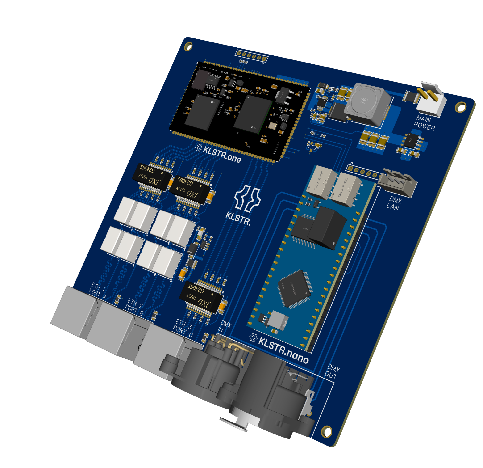
Reference board — 3D render
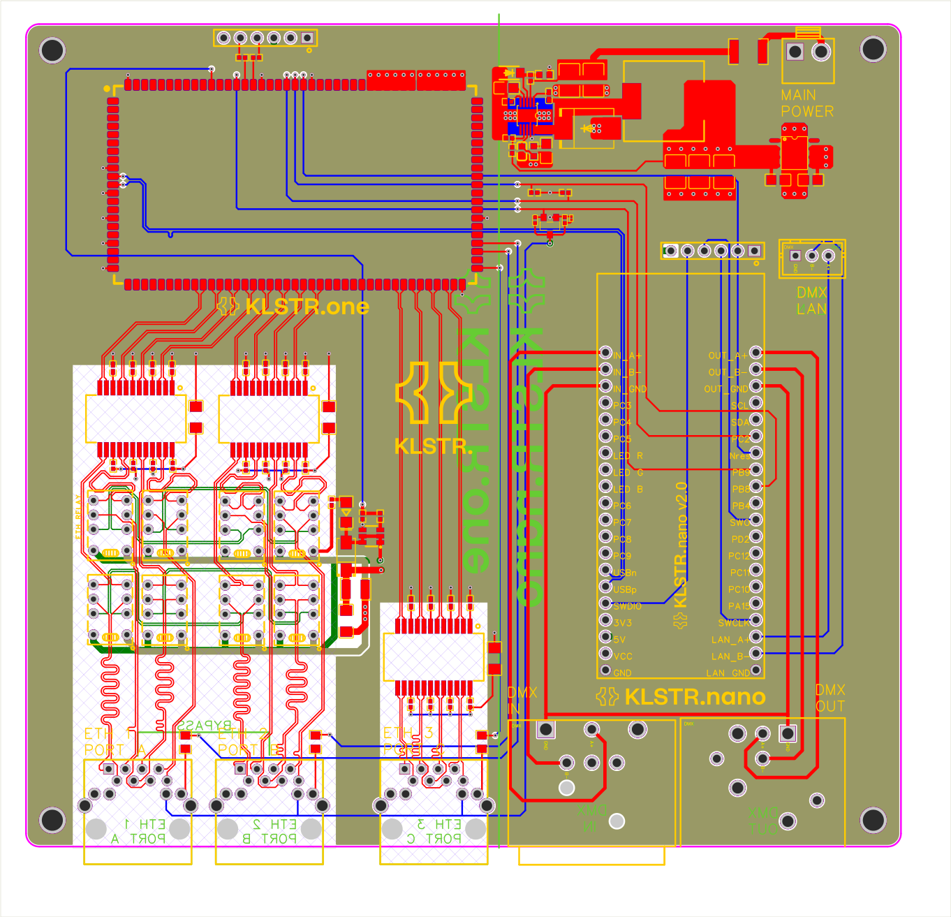
Reference board — PCB layout
Configuration
After wiring, provision each module according to its respective guide:
- KLSTR.one Provisioning — claim, configure network/protocol settings
- KLSTR.nano Provisioning — flash firmware, assign license
In KLSTR.ctrl, the dual-mode pair appears as a single logical device once both modules are online and the heartbeat is active. You can:
- Configure Art-Net/sACN settings on the KLSTR.one side
- Monitor DMX forwarding status on the KLSTR.nano side
- View combined device health (both modules’ firmware, temperature, uptime)
Failover behavior
| Scenario | Behavior |
|---|---|
| KLSTR.one loses power | KLSTR.nano continues operating on the external DMX daisy-chain (DMX_IN → DMX_OUT). Network connectivity is lost. |
| KLSTR.nano loses power | Relay bypass activates — external daisy-chain continuity is maintained. KLSTR.one continues receiving network data but cannot deliver to the host CPU. |
| Both lose power | Relay bypass on KLSTR.nano maintains daisy-chain. No active functionality. |
| Heartbeat timeout | The surviving module logs a warning. No automatic action — the system continues with reduced functionality. |
Next steps
- Fleet Management — managing dual-mode pairs at scale